Hello guys,
i will be updating the whole build log for MultiWii Quadrotor with all diagrams and guides below
please ask for any thing which you don't get:
MULWII QUADROTOR BUILD LOG:first of all get known to some terms:
1.Wii motion Plus(Gyro Module) - WMP or WM+
2. Wii Nunchuk(accelerometer module) - Nunchuk
3. SDA - Data signal lines
4. SCL - Clock signal lines
CONTROLLER BOARD SPECIFICATION:You can build the controller board with several configuration like
1. with Wii Motion Plus Only
2. With Wii Nunchuk Only
3. With WMP+Nunchuk
But if you want to build the quadrotor with the AUTO STABLE function then the 3rd configuration i.e with
WMP+NUNCHUK is preferred.
After deciding which configuration to do( i am assuming 3rd configuration here) you will have to buy the following componenets:
1. Arduino Pro-mini,16MHz,atmel328(
http://www.sparkfun.com/products/9218 or
http://www.rhydolabz.com/index.php?main_page=product_info&products_id=519)
2. Original Nintendo Wii Motion Plus
3.Original Nintendo Wii Nunchuk
(Both WMP and Nunchuk you can get locally from any authorised Wii console distributor in your city or else you can buy it online but buying it locally will reduce the cost. Price for each WMP and Nunchuk
can vary from 1000-1400. And make some inquiry before buying that the product is the Original from brand NINTENDO).
4. FTDI 5V Cable for programming.(
http://www.sparkfun.com/products/9718).
Build Procedure:After getting the Original Nintento Wii Motion Plus and the Wii Nunchuk,you will have to unscrew and open both to get the Gyro and Accelerometer Module from it.
Here is the link to the Video which explains How to Open Both WMP amn Nunchuk to get the module from it.
PART 1:
PART 2:
After watching this video you will come to know that how to get the Gyro and Accelerometer module from the components and how to solder
Nunchuk to the WMP.
Look for the Images below explaning the Pins for WMP and NUNCHUK and their wiring.

My New MultiWii Quadrotor Build And Video

My New MultiWii Quadrotor Build And Video
Dont look at the wiring between the PROMINI and WMP now,we will be doing it afterwards
#After finishing soldering the WMP and NUNCHUK we will turn to the Arduino Promini.Here is the image giving PIN Details of the Promini
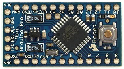
My New MultiWii Quadrotor Build And Video
We will solder the Header pins on the arduino promini Like this from down side

My New MultiWii Quadrotor Build And Video
until now we finished soldering pins to the Arduino Promini and Wiring betwwen the WMP and Nunchuk.
#Here is the connection Diagram between Promini and the Sensors(WMP+NUNCHUK)

My New MultiWii Quadrotor Build And Video
from the above diamgram you can interpret the Circuit.
MAIN CONTROLLER BOARD CONSTRUCTION:Now for wiring up everything together as per the Circuit Diagram in the above image can be done in two ways.
1. Using General Pupose PCB and Soldering.
2. By Making Single Sided PCB at Home.
for the time we will stick to the 1st option to make the JOB simple.
Now you can solder the above circuit in the image by taking reference position of this image.
From this image you will get the idea to where to place the respective components.
My New MultiWii Quadrotor Build And Video
After soldering your own PCB.Your board Will somewhat look like this.

My New MultiWii Quadrotor Build And Video

My New MultiWii Quadrotor Build And Video

My New MultiWii Quadrotor Build And Video
in the above image you can see that i have mounted the Female header pin on the board so that we can easily put Pre-male pin soldered
Promini on this.Main advantage of this arraangement is you can take out the Promini at any time if you want.
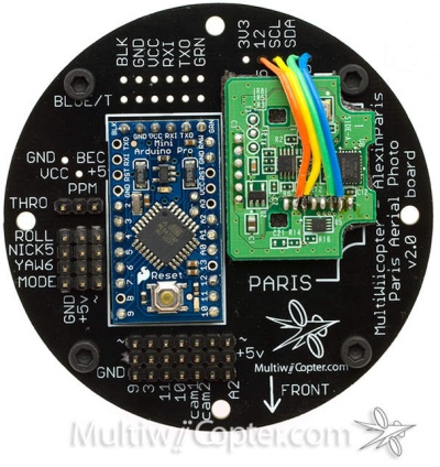
Now You are ready with all the electronics mounted on the board as per shown in the circuit diagram and the whole setup will look
like this:

My New MultiWii Quadrotor Build And Video
The orientation of the WMP and Nunchuk should as shown in the image below:
My New MultiWii Quadrotor Build And Video
And now we will move on to the software part.
MULTIWII SOFTWARE VER1.7:1. First of all you will have to download the ARDUINO ENVIRONMENT Application for uploading firmware to the board
Click on the below link to download the latest version of ARDUINO ENVIRONMENT for your respective OPERATING SYSTEM :
http://arduino.cc/en/Main/Software2. Now you will have to download the MUltiwii COde version 1.7 written by Alex in paris.
Click on the link below to download the Zipped file of the Code and extract it to the folder.
http://multiwii.googlecode.com/svn/tags/MultiWiiV1_7.zipThis zip file contains 2 folders. One contains the main software code and other contains the CONFIGURATOR which i will explain you later.
3. Now you will have to download the PROCESSING which is required for running the configurator.
Click the link below to download the the PROCESSING for your respective operating system:
http://processing.org/download/4. Now if you have the latest version of the JAVA then no need to download otherwise for updating it you can download the
Latest Firmware of the JAVA by clicking on the below link:
http://www.java.com/en/download/index.jsp 5. You will also have to download and Install the FTDI drivers so that your FTDI cable can work with your PC.
Click here to download it:
http://www.ftdichip.com/Drivers/CDM/CDM20814_Setup.exeNow we have finished downloading all the Required sofwares for uploading the firmware.
now we will move on to how to upload the Firmware to the Arduino promini.
UPLOADING FIRMWARE TO THE ARDUINO PRO-MININow open the application file from the latest ARDUINO ENVIRONMENT which we have already downloaded.
After opening it you will see this window:
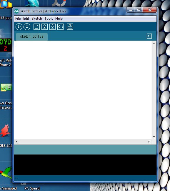
My New MultiWii Quadrotor Build And Video
Now go to Tools option given on the Bar and from there select the Proper Board as shown below:
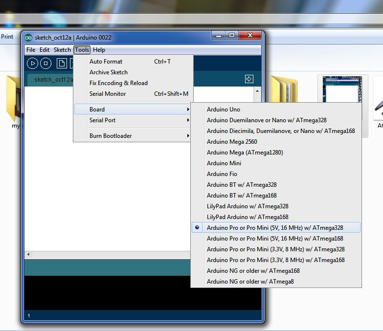
My New MultiWii Quadrotor Build And Video
Now go to File option and open the firmware from the folder where you have saved it with the name- MultiWii1_7
The Code is self explanatory.There are only some #defines which you will have to activate by uncommenting it as per your configuration.
After doing the necessary corrections now your code is ready for upload.
#UPLOADING FIRMWARE:Now connect the FTDI cable to the Arduino promini first as shown in the image below:

My New MultiWii Quadrotor Build And Video
look at the proper orientation of the cable and the Promini.
Now connect the other USB end to the USB PORT on your PC.
From your PC's Device manager you will come to know the port number of your FTDI cable.
Select the same port in the ARDUINO SOFTWARE
by going to Tools>Serial Port>( Your COM PORT numbar)
After that click on the
VERIFY button given below the bar which will start compiling the software.Once it get compiled
push the Reset button on the Arduino Promini and after few second.
Click on the UPLOAD button in arduino which will upload the software to the Promini.
It takes around 20 second for the Firmware to get Uploaded.
After Uploading the firmware to your board.now your board is ready for test with MultiWii cofigurator.
TESTING THE MULTIWII BOARD WITH THE MULTIWII CONFIGURATOR:Now the Multiwii Firmware which we have downloaded contain 2 folders on of that folder contains the Configurator.
So go to that folder and Open the respective folder according to your Operating System.
Before opening the MUltiWiiConf1_7.exe connect your board through FTDI cable to the PC and then open the Configurator.
Configurator takes sometime to open.This opening time can vary PC to PC so dont worry if your configurator is taking time to get open.
But check that you have downloaded all the necessary software which i have already mentioned.
After opening you will see following window:
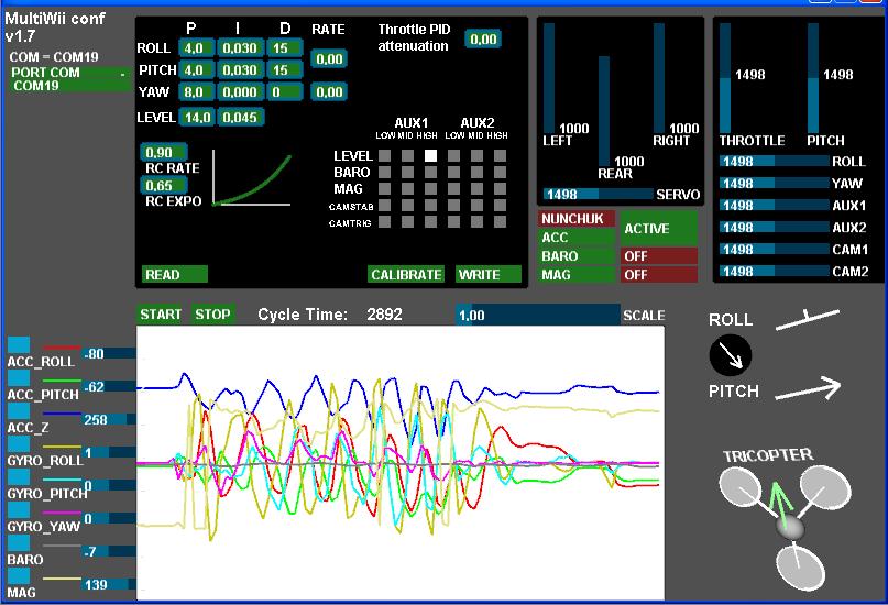
My New MultiWii Quadrotor Build And Video
In your case,at LEFT UPPER corner you will find the list of the Ports.From that you will have to choose the Port Number which you have specified for the FTDI cable.
Initially Port number will be shown with Brown Background but as soon as you select the port it will turn to Green.
After that Click on the START to read the values from the board.
Here are some video's which explains about how to use the Configurator: